


Have you ever found yourself puzzled by the intricate maze of wires and circuits that power your home? Understanding the electrical wiring diagram of a house can seem daunting, but it’s incredibly helpful for both troubleshooting and planning any future improvements. In this detailed guide, you’ll find everything you need to know about how your home’s electrical system works, including diagrams, components, and safety tips.

Understanding Electrical Wiring Diagrams
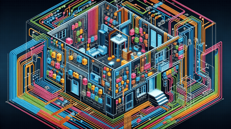
An electrical wiring diagram is essentially a roadmap for your home’s electrical system. It illustrates how various components, such as outlets, switches, and fixtures, are interconnected. By utilizing this diagram, you can identify circuits, understand power distribution, and gauge how to expand or repair your system safely.
Why Electrical Wiring Diagrams Are Important
- Safety: Knowing how your home’s wiring system operates helps prevent electrical fires and other hazards.
- Troubleshooting: When issues arise, having access to a wiring diagram allows you to pinpoint the problem quickly.
- Renovations and Upgrades: Whether you’re adding new outlets or planning a major renovation, a wiring diagram will guide your decisions.
Key Components of Electrical Wiring
Before we get into specific diagrams, it’s essential to familiarize yourself with the key components that you’ll frequently encounter.
Main Service Panel
The main service panel is the powerhouse of your home’s electrical system. It distributes electricity to various circuits throughout the house. Typically located in a basement or utility room, it also houses the circuit breakers that help protect your home from overloads.
Circuit Breakers
Circuit breakers act like gatekeepers, controlling the electric flow to different areas of your home. They trip when there’s an overload or short circuit, preventing potential disasters.
Wiring Types
Different types of wiring materials are used throughout your home. The most common types include:
| Type | Description |
|---|---|
| NM Cable | Non-metallic wiring, ideal for general usage. |
| UF Cable | Underground feeder cable, perfect for outdoor use. |
| BX Cable | Flexible metallic tubing, often used in commercial spaces. |
| Romex | A brand of NM cable frequently used in residential wiring. |
Outlets and Switches
Outlets and switches are the control points for electricity use in your home. Outlets permit you to plug in devices, while switches regulate lighting and other electrical fixtures.
Lighting Fixtures
From ceiling lights to wall sconces, lighting fixtures serve as the primary way you illuminate your home. Each fixture must be wired to a corresponding switch and power source.
Basic Electrical Wiring Symbols
Understanding the symbols used in electrical diagrams can be the key to reading them easily.
| Symbol | Description |
|---|---|
| Line | Represents a wire or conductor. |
| Circle | Denotes an outlet or electrical device. |
| Switch | Illustrates light switches. |
| Battery | Depicts a source of power, such as a battery. |
Color Coding of Wires
To maintain organization and enhance safety, wires are color-coded based on their function. Here’s a breakdown:
| Color | Function |
|---|---|
| Black | Hot wire carrying electricity. |
| White | Neutral wire returns current. |
| Green | Ground wire for safety. |
| Red | Secondary hot wire (in 220v systems). |
Common Electrical Wiring Diagrams in a Typical House
Simple Circuit Diagram
A simple circuit diagram illustrates how power flows from the main service panel to various devices. Typically, it shows the path from the breaker to the light fixtures and outlets.
-----> [Battery] -----> [Switch] -----> [Light Fixture] In this case, electricity flows through the battery, is controlled by a switch, and powers a light fixture, demonstrating a straightforward electrical circuit.
Multi-Room Circuit Diagram
In larger homes, circuits may power multiple rooms. Understanding how these circuits branch off is crucial.
[Main Panel] —–> [Circuit Breaker] | ———————– | | | [Living] [Kitchen] [Bedroom] [Outlets] [Outlets] [Outlets]
In this multi-room circuit diagram, one breaker supports various rooms, each with unique outlets.
240V Circuit Diagram
For larger appliances like dryers or ovens, a 240V circuit diagram is necessary to illustrate the heavier power load.
-----> [Breaker 240V] -----> [Appliance] | [Hot wires] This diagram shows a dedicated circuit for an appliance, ensuring adequate power flow and safety.


Electrical Wiring Codes and Regulations
Understanding local electrical codes is vital for anyone planning to work on their home’s wiring. Here are some critical points to keep in mind.
National Electrical Code (NEC)
The NEC sets the standards for electrical wiring installations in the United States. It covers a wide array of topics, including:
- Proper wire sizing
- Safe installation practices
- Grounding requirements
Familiarizing yourself with these regulations ensures that your wiring is both safe and compliant.
Local Building Codes
In addition to the NEC, your local area may have specific building codes that must be adhered to. It’s essential to check with your municipal building office or a licensed electrician to ensure compliance.
Safety Precautions When Working with Electrical Wiring
Your safety is paramount when dealing with electrical systems. If you ever decide to embark on a wiring project, keep these safety tips in mind.
Turn Off Power
Always switch off the breaker supplying power to the area where you’re working. Consider using a multimeter to double-check that no current is flowing.
Use Protective Gear
Wearing insulated gloves and goggles can prevent injury from shock or flying debris during installation or repairs.
Work with a Buddy
When dealing with electrical systems, it’s a great idea to have someone with you. In an emergency, a buddy can seek help if necessary.
Know When to Call a Professional
If you’re unsure about any aspect of electrical work, calling a licensed electrician is the smartest option. It’s better to be safe than to risk serious injury or damage.
Planning Your Home’s Electrical System
If you’re considering building or renovating, planning your electrical system carefully will save you a lot of headaches later.
Determine Your Load Requirements
Assessing what electrical devices you want to power will help you figure out your load requirements. For example, if you plan to have multiple high-wattage appliances, be prepared to install additional circuits.
Design Your Circuit Layout
Once you know your load, sketch out a circuit layout. This going to help you visualize where outlets, switches, and fixtures will go, optimizing for both function and aesthetics.
Consider Future Expansion
When planning your electrical system, account for future needs. Adding extra outlets or even another room later will be much easier if you plan for it upfront.
Troubleshooting Common Electrical Issues
Even with a well-planned electrical system, problems can arise. Familiarizing yourself with common issues can save you time and frustration.
Flickering Lights
If your lights flicker, it could indicate a loose connection, an overloaded circuit, or an issue with the fixture itself.
Frequent Breaker Trips
When a breaker frequently trips, it often signals overload, a grounding issue, or faulty equipment. An electrician can help diagnose the problem safely.
No Power to Outlets
If certain outlets have no power, check the circuit breaker panel and inspect the outlet itself for loose wiring.
Conclusion
Getting comfortable with the electrical wiring diagram of a house might seem overwhelming at first, but understanding the fundamentals can empower you to take better care of your home. Whether you’re planning renovations, troubleshooting issues, or simply wanting to learn more about how your home functions, having a solid grasp of your electrical system is crucial. Stay safe, use resources wisely, and don’t hesitate to call in a professional when in doubt!